|
|

|
Home / Support / Carbon Fiber Reinforcement / Visual Application Guide Carbon Fiber Foundation Wall Repair — Visual Application GuideThis guide covers how carbon fiber straps are placed, oriented, and supported across the most common foundation wall conditions. Images are grouped by topic — click any thumbnail to view full size. Guidance applies to both block and poured concrete walls unless otherwise noted. Contents: Strap Placement | Top of Wall Support | Base Support | Corner Repair | Window Support | Carbon Fiber Explained
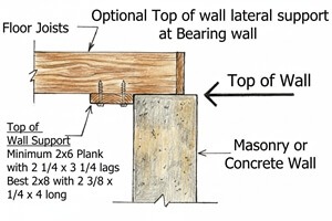
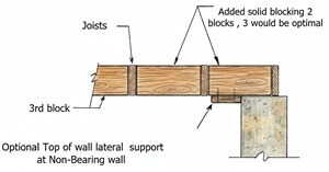
Carbon Fiber Strap Placement — Block and Poured WallsCarbon fiber straps run vertically from floor to ceiling and are spaced a maximum of 4 feet apart on centre. Straps are always oriented perpendicular to the crack direction — vertical for horizontal cracks, diagonal for diagonal cracks. Placing a strap parallel to a crack does not engage its tensile strength and is incorrect. Obstacles such as pipes, electrical panels, and window frames interrupt strap runs. Work around them by placing straps on each side of the obstacle as close as the surface allows. Where a window or door opening prevents a full-height strap from running, place straps immediately beside each edge of the opening. On block walls, straps span both block faces and mortar joints — the bond surface must be ground flat across the full strap width including any raised mortar joints before application. Spacing adjustment: 4 feet is the maximum. Spacing can be reduced to 3 feet or closer where wall condition is poor, deflection is significant, or the repair is in a high-load area such as between windows or below a beam bearing point. Top of Wall Lateral Support MethodsTop of wall lateral support prevents the top course of the foundation wall from rotating inward under soil load. It is not always required. If the floor framing bears directly on the wall and makes solid contact across the top of the wall, the floor system itself provides adequate lateral restraint and no additional support is needed. Support is required when the top of the wall has begun to rotate inward, when framing runs parallel to the wall with no direct bearing, or when the repair spans a long unsupported wall section. The method depends on the floor framing orientation at the wall being repaired. Bearing wall — joists perpendicular to wall: A minimum 2x6 plank (2x8 preferred) is fastened to the face of the floor joist with a minimum of two lag screws — ¼ x 3¼ inch minimum, 3/8 x 4 inch preferred. The plank bears firmly on the top of the wall and transfers lateral load from the wall directly into the floor joist system. Shim if needed to ensure full contact along the wall top. Non-bearing wall — joists parallel to wall: Solid blocking is installed between the two nearest joists and extended to a third joist bay where space permits. Minimum two joist bays of blocking creates a rigid connection from the wall top into the floor system. Three bays is optimal where access allows. Pocket beam location: Where a wood beam bears in a wall pocket at a non-loaded end wall, a 4 inch heavy angle iron bracket is mounted around the bottom and sides of the beam at the wall joint. The bracket transfers lateral wall load into the beam without bearing on the beam top, preserving the beam's load path. This method applies only at end walls where the beam does not carry floor load from the wall direction. Base Footing Support MethodsBase support prevents the bottom course of the foundation wall from sliding inward along the footing under lateral soil load. Whether it is required depends on the wall type and the condition of the base. Poured concrete walls: The concrete floor slab is poured tight against the base of the wall and bonds to it. When the slab is properly placed and the bottom of the wall is plumb and stable with no inward movement, the floor slab itself acts as a rigid horizontal brace. No additional base anchor is required in this condition — the slab provides full lateral resistance at the base. Block walls: Concrete block does not bond to the floor slab the way poured concrete does. Where the base of the wall has shifted inward or the bottom block courses show movement, a wide heavy angle iron bracket is bolted to the concrete floor slab tight to the base of the wall. The bracket is anchored with a minimum of two concrete floor anchors and prevents further inward sliding. If the floor slab is poured tight against the base of the block wall and the bottom courses are plumb and stable with no movement, the bracket may not be required — assess each situation individually. Foundation Corner RepairFoundation corners experience soil pressure from two directions simultaneously. A corner that is cracking or rotating must be reinforced on both wall faces to address both load directions. A single strap on one face of a corner does not tie the corner together. Carbon fiber straps at corners are applied horizontally, spaced every 2 feet vertically up the corner, and wrap continuously around the corner, extending a minimum of 4 feet onto each wall face. The continuous wrap ties both wall faces together at the corner joint, preventing the corner from spreading, separating, or rotating under lateral load. Mechanical anchors are installed at each strap end to help keep carbon in place during cure. Corner repair is the appropriate method for early-stage corner cracking and rotation where deflection is limited. Corners with significant deflection or separation may require exterior excavation and backfill replacement to reduce the lateral load before interior CF strapping is applied. Window and Opening ReinforcementBasement windows and door cutouts are the most common stress concentration points in a foundation wall. The opening interrupts the continuous wall section, leaving the wall on each side of the opening as a narrower column with reduced stiffness. Cracks most commonly radiate diagonally from the corners of window openings under lateral soil load. Vertical straps beside the opening: Place a vertical strap tight to each side of the window frame, running the full wall height. Where the panel between two adjacent windows is too narrow for standard spacing, straps may be placed side by side directly with no gap between them. Horizontal strap at crack level: Where cracks radiate from window corners, a horizontal strap is applied directly over the wall at the window sill or header level, crossing the vertical straps at 90 degrees. The horizontal strap must extend at least 2 feet past each adjacent vertical strap on both sides to develop adequate bond length. The combination of vertical and horizontal straps in an H- or T-shaped pattern ties the wall together at the most vulnerable points, especially with Block wall construction. Note on crack treatment before strapping: On poured concrete walls, inject any structural horizontal cracks with structural epoxy before applying carbon fiber. On block walls, tuckpoint any failed mortar joints — do not inject block walls with epoxy or polyurethane, as block hollow cavities prevent injection from reaching them. How Carbon Fiber Works — Weave Type and Load DirectionWeave type determines efficiency. Carbon fiber fabric is manufactured in two main configurations. Bidirectional plain weave has fibers running in two directions — the cross-fiber tow adds compliance and allows the fabric to stretch slightly under load, which reduces the effective stiffness available to resist wall movement. Unidirectional fabric (UD) runs all structural fibers in one direction with only a light cross-tow to hold the fabric together during handling. Under load, all tensile strength acts in one direction with minimal stretch. For foundation wall repair, unidirectional fabric oriented perpendicular to the crack delivers significantly greater resistance per unit of material. Using bidirectional carbon lowers its rating by 50% in each direction. All NextStar carbon fiber products are unidirectional UD fabric. Strap direction is critical. Carbon fiber only works in tension — it holds the crack faces together when oriented to cross the crack at 90 degrees. A strap placed parallel to a crack runs along the crack face rather than across it. Instead of holding the crack together, the load is transferred back to the crack and concentrates there. The result is that a parallel strap provides little to no restraint and can actually increase stress at the crack tip. Carbon fiber must always be perpendicular to the crack — vertical for horizontal cracks, diagonal for diagonal cracks, horizontal only in specific cases such as window crack bridging where the crack direction warrants it. Related Pages |
|
|